Español
 Русский
 Francés
 Português
 ภาษาไทย
 Indonesia
 Việt
 العربية
 Melayu



Standardized Installation Procedure For Fully Automatic Veneer Dryers
Standardized Installation Procedure For Fully Automatic Veneer Dryers
For plywood manufacturing plants, the veneer dryer serves as the core equipment of the entire production line. Whether utilizing a roller, flap, or mesh-belt design, these fully automatic veneer dryers are extensive, continuous, integrated systems. They comprise the main dryer body, servo-driven conveying systems, vacuum-assisted feeding mechanisms, biomass heating systems, dust removal units, electrical control systems, and moisture content detection modules. The precision of the installation directly dictates whether the veneer will track correctly or suffer from warping and uneven moisture content during operation; it also significantly impacts energy consumption, failure rates, and the overall service life of the equipment. A standardized, step-by-step installation process is essential for ensuring stable, long-term production.
I. Pre-Installation Preparation and Foundation Inspection
Before commencing on-site construction, it is necessary to complete technical briefings, site verification, and foundation inspections. The project manager, the plant’s equipment supervisor, and the installation team must collectively review the foundation drawings, assembly diagrams, electrical schematics, and heating pipeline layouts. This ensures the production line is correctly configured—aligning the infeed end with the rotary-peeling line or feeding table, and the outfeed end with the stacking station—while also accounting for maintenance access, lifting clearance, and the designated placement for the biomass burner and water-film dust removal system.
On-site verification of the concrete foundation is critical. Key checks include foundation elevation, centerlines, and the coordinates of anchor bolt holes. It must be confirmed that the concrete has reached its design-specified curing strength and that the surface is clean, free of loose cement paste, and devoid of depressions. As a long-span, continuous-conveyance system, the overall levelness of the veneer dryer is of paramount importance; any deviation in the foundation can lead to uneven loading on the rollers, misalignment of conveyor chains, and abnormal noise from servo mechanisms.
Simultaneously, an inventory of all delivered components should be conducted—including main dryer sections, frames, roller/flap assemblies, insulation panels, fans, heat-exchange piping, biomass burners, dust collection units, moisture sensors, servo motors, control cabinets, and seals. Each component should be properly labeled and protected to prevent damage or moisture exposure, particularly for sensitive items like insulation materials and precision sensors. Prepare a crane, precision level, torque wrench, and leak-detection tools; verify the locations for power supply, circulating air ducts, and drainage/discharge ports.
II. Layout, Positioning, and Leveling of the Base
Using the reference points from the blueprints, mark the centerlines (longitudinal and transverse) and elevation control lines for the entire machine, and indicate the installation position for each frame section. Proceeding from the infeed end to the outfeed end, hoist each frame base into position. Place shims beneath the bases and use a precision level to calibrate the levelness and straightness of each section. Maintain strict control over the longitudinal and lateral alignment of the entire machine to ensure all frame sections are perfectly coaxial, preventing any vertical misalignment or lateral offset.
Once the bases are leveled, insert the anchor bolts and tighten them initially. After verifying that the alignment remains unchanged, proceed with secondary grouting. During the curing period, avoid any hoisting or impact-related activities. Once the grout has fully cured, tighten the anchor bolts in a diagonal pattern to the specified torque, and re-verify the machine’s reference alignment. This step is the foundation for the stable operation of the entire system; many subsequent issues—such as jammed rollers or the misalignment (drifting) of veneer sheets—often stem from a failure to properly level and calibrate the base.
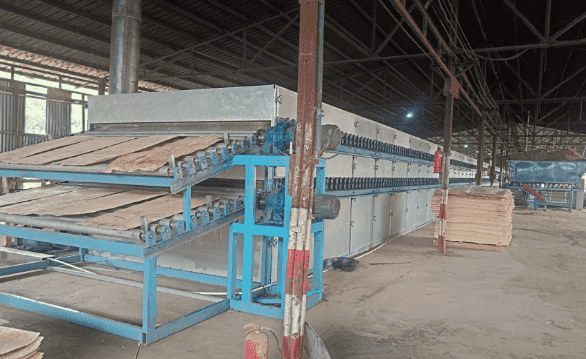
III. Assembly of the Main Unit and Conveying Mechanism
With the bases secured, begin hoisting the main drying unit housing and insulation chambers into place, connecting the individual drying sections. Ensure all joints are properly sealed using high-temperature-resistant sealing materials to prevent hot air leakage, minimize heat loss, and maintain a suitable workshop environment. Install the internal roller assemblies (or flap mechanisms), guide/pressure rollers, chains, and synchronous drive components. Adjust the parallelism of the rollers and the tension of the chains to ensure all conveying units operate in perfect synchronization, thereby preventing veneer sheets from drifting, jamming, or sustaining surface scratches. Next, the front-end automatic vacuum feeding system and the back-end discharge and panel-turning mechanism are installed. The height of the suction cups and the timing of the panel-feeding sequence are adjusted to ensure that each veneer enters the drying chamber smoothly, without collisions or overlapping. Thermal insulation panels are installed, and an extra-thick insulation layer is applied to minimize heat loss from the chamber, ensuring the stability of the low-temperature, slow-drying process.
IV. Integration of Heating, Dust Removal, and Piping Systems
Once the mechanical structure of the main unit is assembled, the heating system is integrated. Components—including the biomass burner, heat-exchange air plenum, waste-heat recovery ducts, circulation fans, and induced-draft fans—are positioned and connected. The hot-air piping is assembled according to the technical drawings, with all flanges tightly sealed and wrapped in insulation. This system determines the uniformity of the hot air, which is critical for controlling color consistency across the veneers and preventing localized scorching or cracking.
A water-film dust removal system is installed, with flue-gas ducts and water supply/drainage piping connected. Leak testing is performed, and drainage and overflow lines are checked to ensure they are clear, meeting environmental emission standards. Additionally, waste-heat recovery piping is installed to capture and reuse exhaust heat from the kiln, achieving an energy-efficient design. After all air and flue-gas ducts are installed, a leak check is conducted to identify and seal any air leaks.
V. Wiring for Electrical, Sensing, and Intelligent Control Systems
Electrical installation strictly follows the control schematics. Wiring for the main control cabinet, servo drives, in-line moisture analyzers, temperature sensors, pressure probes, fan motors, and actuators is routed separately—keeping high-voltage and low-voltage lines apart—and grounded reliably to ensure electrical safety.
AI-based temperature probes and moisture-detection probes are installed at precise locations as required by the process, ensuring real-time data collection for temperature and veneer moisture content across different zones within the chamber. Once wiring is complete, all connections are verified for tightness and clear labeling. Limit switches, emergency-stop buttons, and safety interlocks are integrated into the system to ensure robust safety protection logic. Before powering on the equipment, the wiring is verified and insulation testing is performed to eliminate any risks of short circuits or loose connections. VI. No-Load Trial Run and Step-by-Step Calibration
Once powered on, the equipment enters the no-load commissioning phase—a critical step for verifying assembly quality. Begin by individually testing each independent mechanism—such as the circulation fans, induced-draft fans, conveyor servo systems, flipper mechanisms, and vacuum-suction feeding cups—to ensure correct rotation direction and check for any unusual noises, abnormal vibrations, or mechanical binding.
Next, conduct a continuous no-load run of the entire machine for several hours. Key monitoring points include the smooth operation of rollers and flippers, chain synchronization, temperature rise in fan bearings, servo response, zonal hot-air regulation, and sensor signal feedback. During this phase, perform adjustments such as correcting belt/chain tracking, fine-tuning chain tension, and calibrating damper openings to rectify any mechanical deviations remaining from the installation stage. On the electrical control side, commission the multi-stage temperature control logic and test functions such as automatic heating, constant-temperature maintenance, and over-temperature protection.
VII. Trial Drying with Material, Process Parameter Calibration, and Final Acceptance
Once the no-load testing is successfully completed, proceed to trial production using standard veneers commonly processed at the facility (e.g., eucalyptus, rubberwood, or engineered wood veneers). Technical staff will work alongside the facility’s operators to configure drying speeds, zonal temperatures, and airflow rates. They will monitor the moisture content and surface flatness of the veneers as they exit the machine, while tracking metrics such as moisture uniformity, warping, and cracking to continuously optimize the drying curve.
Based on the trial drying results, fine-tune the heating supply, airflow velocity, and conveyor speed to keep moisture content within the specified process range. This ensures the veneers remain flat with minimal color variation, meeting the requirements for subsequent hot-pressing and gluing processes. Simultaneously, evaluate energy consumption—both under no-load and operational conditions—and verify that the biomass combustion and dust-removal systems are functioning stably and meeting emission standards.
Once all performance indicators meet the contractual requirements, compile the installation records, commissioning reports, and technical documentation (drawings, etc.). Provide comprehensive training for the facility’s operators—covering the use of automated programs, parameter adjustments, routine inspections, basic troubleshooting, and key maintenance procedures—to finalize the project acceptance and officially hand over the equipment for production. VIII. Notes on Installation and Commissioning
For this long-line production system, ensuring proper leveling and straightness is the top priority; do not force the connection of misaligned machine frames.
The hot-air system must be thoroughly sealed; air leaks not only increase energy consumption but also lead to uneven drying.
Moisture probes and temperature sensors are precision components; take care to prevent damage from high temperatures during installation or welding.
Regularly inspect the biomass heating system and dust-extraction ductwork to prevent blockages caused by dust accumulation.
Do not operate the equipment at full load for extended periods before commissioning is complete, as this could exacerbate any underlying assembly issues and lead to component damage.
Shine Machinery’s fully automatic veneer dryers offer a one-stop service—from site surveying and technical drawing to on-site installation, intelligent commissioning, and after-sales maintenance. We provide standardized, on-site installation for various models, including roller-type, flap-type, mesh-belt, and high-capacity multi-layer systems. Designed to integrate seamlessly into both domestic and international plywood production lines, our equipment ensures the stability of low-temperature, slow-drying processes, thereby reducing the need for veneer rework.